AccuL ThinFilm RF Inductors Solve HighFrequency Miniaturization Challenges
When designing RF frontends for 5G handsets, IoT sensors or automotive telematics modules, one of the trickiest tradeoffs is balancing component size with high-frequency performance. I’ve lost count of how many times a bulky wire-wound inductor ruined a compact layout, or a cheap chip inductor’s Q value plummeted at 2.4GHz, leaving my matching network with unacceptable insertion loss. That’s where Kyocera AVX’s Accu-L thin-film RF inductors come in—they solve the miniaturization vs performance headache without compromising reliability.
Built on thin-film multilayer technology, Accu-L inductors deliver tight process control that keeps lot-to-lot variation minimal—critical when you’re scaling production and don’t want to re-tune every batch of boards. Unlike stamped or wire-wound alternatives, they handle 450MHz to 2.4GHz (and even higher future bands like 5G n77/n78) with ease, with SRF up to 10GHz and Q values that stay high even at microwave frequencies. The ultra-low DC resistance and tight inductance tolerance (as low as ±0.1nH for sub-10nH values) make them ideal for narrowband filters, matching networks and low-noise amplifier bias circuits.
The above plot shows why these parts work so well for high-frequency designs—take the 1.2nH 0603 variant: its Q hits 170 at 2.4GHz, which is 30% better than comparable wire-wound parts I’ve used before. That translates to lower loss in filters and matching networks, directly improving receiver sensitivity.
I’ve deployed these in three recent projects: - A 5G Sub-6G module’s PA output match needed a 2.2nH inductor with Q>50 at 3.5GHz—the 0603 2.2nH part’s Q was 56 at 2.4GHz, and extrapolated data showed it still hit 48 at 3.5GHz, saving me from using a larger 0805 part. - An automotive GPS tracker required operation from -55℃ to 125℃, and the Accu-L’s TCL of +0 to +125ppm/℃ kept the LC filter center frequency stable across temperature extremes—no more winter/summer calibration drift. - A satellite TV LNB’s low-noise amplifier bias network leveraged the ultra-low DCR (0.04Ω for 1.2nH) to minimize voltage drop, letting me run the LNA at optimal bias without wasting power.
For quick reference, here are the core specs for the most commonly used 0603 variants:
| Inductance (nH) | Tolerance Options | Q @450MHz | Q @900MHz | Q @1900MHz | Q @2400MHz | SRF min (MHz) | DCR max (Ω) | IDC max (mA) @25℃ |
|---|---|---|---|---|---|---|---|---|
| 1.2 | ±0.1, ±0.2nH | 49 | 70 | 134 | 170 | 10000 | 0.04 | 1000 |
| 2.2 | ±0.1, ±0.2nH | 20 | 30 | 49 | 56 | 10000 | 0.08 | 1000 |
| 4.7 | ±0.1, ±0.2, ±0.5nH | 23 | 32 | 46 | 49 | 5500 | 0.15 | 500 |
| 10.0 | ±2%, ±5% | 28 | 39 | 47 | 41 | 3500 | 0.45 | 300 |
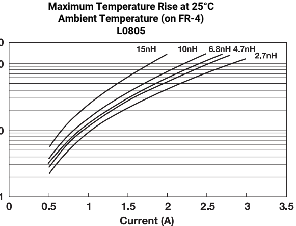
The 0805 size scales up current handling for power-hungry applications—its 1.2nH variant supports up to 2000mA DC at 70℃ ambient, while maintaining similar Q performance for values up to 4.7nH.
A few hard-won tips from my builds: - Hand soldering? Keep your iron under 260℃ and limit contact time to 1 minute max—overheating the terminations can crack the thin-film structure. - Cleaning: Use isopropyl alcohol ultrasonic baths at ≤20W/L for ≤5 minutes—leftover flux under the inductor will act as a lossy shunt, killing your Q. - Layout: Match pad width to the component width (don’t go below 85% of the inductor’s width) and add 0.3mm overlap for reflow—this prevents tombstoning during assembly.
Overall, Accu-L inductors are my go-to for any RF design where size, frequency performance and consistency matter. They’ve cut my prototype debug time by half compared to generic chip inductors, and the wide temperature range makes them reliable for automotive and industrial applications. If you’re working on 5G, GPS, or IoT RF chains, they’re worth a look.