TNPW e3 High Stability Thin Film Flat Chip Resistors for Demanding Designs
When you’re designing automotive ECUs, industrial motor drives, or medical monitoring gear, resistor drift isn’t just a spec sheet footnote—it’s a silent killer of long-term reliability. I’ve debugged more than one field failure traced back to sulfur ingress corroding thick film elements, or moisture-induced resistance shifts throwing off precision sensor front ends. That’s why I keep coming back to Vishay’s TNPW e3 series when the application can’t tolerate “good enough” passive performance.
What sets these thin film chips apart isn’t just the numbers (though we’ll get to those). It’s the stability you can actually bank on. The homogeneous metal alloy film on Al₂O₃ ceramic gives you a temperature coefficient down to ±10 ppm/K, and laser trimming keeps tolerance tight without micro-cracking the substrate—a lesson I learned the hard way with cheaper alternatives that failed thermal cycling in aerospace prototypes.
Let’s talk real-world specs. If you’re pushing 1206 footprints, you get up to 0.52 W dissipation at 70 °C—plenty for filtering or current sensing in 24 V automotive rails. But the real win is the 175 °C max film temperature. In under-hood ECUs where ambient spikes past 125 °C, that headroom means you’re not derating to useless levels. And yes, they’re AEC-Q200 qualified, PFAS-free, and shrug off 85 °C/85 % RH for 1000 hours with |ΔR/R| < 0.1 %. I’ve seen competitors’ parts double that drift in half the time.
Sulfur resistance is another non-negotiable for me. These pass ASTM B 809 and ANSI/EIA-977 testing—no silver sulfide creep, even in exhaust gas sensor interfaces. For medical devices, the low noise and linearity matter more than most realize. I’ve used the ±0.1 % tolerance variants in bridge circuits where a 0.05 % shift would throw calibration off-spec.
Now, let’s cut through the parametric noise. Here’s what actually matters for selection:
| Imperial Size | Metric Code | Resistance Range | Power @ 70°C | Temp Coefficient Options |
|---|---|---|---|---|
| 0201 | RR0603M | 22 Ω – 40 kΩ | 0.075 W | ±25 ppm/K |
| 0402 | RR1005M | 10 Ω – 100 kΩ | 0.130 W | ±50 / ±25 / ±15 ppm/K |
| 0603 | RR1608M | 1 Ω – 332 kΩ | 0.210 W | ±50 / ±25 / ±15 ppm/K |
| 0805 | RR2012M | 1 Ω – 1 MΩ | 0.260 W | ±50 / ±25 / ±15 ppm/K |
| 1206 | RR3216M | 1 Ω – 2 MΩ | 0.520 W | ±50 / ±25 / ±15 ppm/K |
| 1210 | RR3225M | 10 Ω – 3.01 MΩ | 0.520 W | ±50 / ±25 / ±15 / ±10 ppm/K |
One trap to avoid: don’t assume “rated power” means you can run at 70 °C indefinitely. The film temperature limit is 175 °C, and that depends on your PCB thermal design. I’ve seen 1206 resistors fail prematurely because the layout starved them of copper—always check the thermal resistance app note (Vishay doc 28844) before finalizing your stack-up.
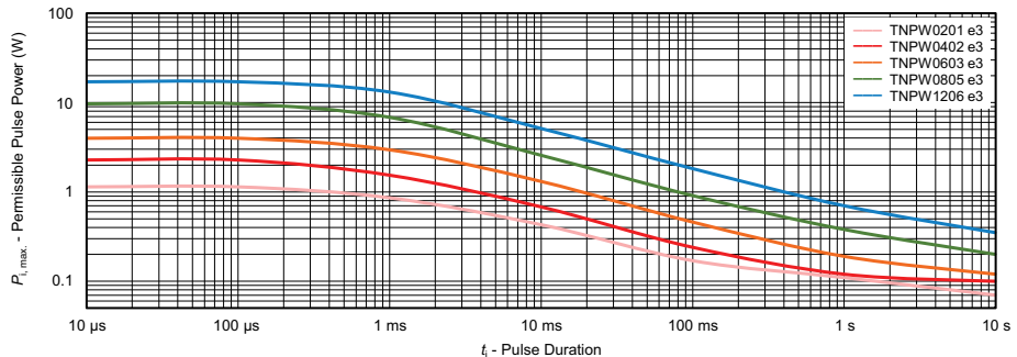
For pulse loads, these handle 1.2/50 μs surges without flinching, but watch the repetition rate. Single pulses are fine up to the voltage rating, but continuous pulsing needs derating. I learned this debugging a power supply snubber where 10 kHz pulses pushed the part beyond its safe operating area.
If you need ultra-precision (≤ ±0.05 % tolerance, ±2 ppm/K TCR), look at the TNPU e3 sister series—same reliability, tighter specs. For high-voltage designs, TNPV e3 is the play. And if you’re in space or defense, the ESCC-qualified TNPS variants are worth the extra cost.
Bottom line: TNPW e3 isn’t the cheapest thin film resistor out there, but it’s the one I reach for when the design can’t afford a recall. Automotive, industrial, medical—anywhere stability beats BOM cost. Just don’t skip the thermal math, and you’ll sleep better knowing your resistors won’t drift out of spec before the product’s end-of-life.