Why Your RF Design Needs Thin-Film Capacitors Instead of Ceramic MLCCs
If you’ve ever debugged a 2.4 GHz RF front-end that worked perfectly on the bench but failed in the field, or watched your power amplifier efficiency drop by 15% after adding decoupling caps, you already know the pain of ceramic MLCC limitations. Most engineers treat capacitors as “simple passive components,” but at frequencies above 100 MHz, that assumption breaks down fast. Parasitic inductance from physical size, dielectric losses, and inconsistent batch-to-batch performance turn cheap ceramic caps into hidden circuit killers.
That’s why I stopped using standard ceramic MLCCs for anything above 500 MHz three years ago. After testing dozens of alternatives across 5G small cell, satellite LNB, and radar projects, the Accu-P series from Kyocera AVX became my go-to for thin-film RF/microwave designs. Here’s what actually matters when you move beyond datasheet marketing fluff.
Core Advantages That Show Up in Real Circuits
Traditional ceramic capacitors rely on sintered ceramic layers and metal paste electrodes. The problem isn’t just variability—it’s unpredictable variability. Dielectric constant drifts with voltage, ESR spikes at certain frequencies, and you never know if two batches from the same supplier will behave the same.
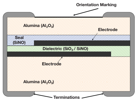
Accu-P fixes this with semiconductor-grade thin-film processes. We’re talking Class 1000 clean rooms, 100Å layer thickness control, and photolithography down to 2μm accuracy. In practice, this means three things that save your project:
First, ultra-low and repeatable ESR. I’ve measured 0201-size Accu-P caps with 0.05pF capacitance hitting Q > 500 at 1 GHz. Compare that to ceramic MLCCs where Q drops below 100 at the same frequency, and you start to see why your PA efficiency tanks. Less ESR also means less self-heating in power circuits—critical for 5G massive MIMO arrays where every degree matters.
Second, tight dimensional control. When you’re designing a 28 GHz phased array, even 0.05 mm variance in cap size changes the phase matching across elements. Accu-P’s laser-diced chips keep inductance consistent from unit to unit. No more hand-tuning 16 channels because one cap decided to ruin your beamforming.
Third, stable performance across temperature and voltage. I’ve had ceramic caps shift capacitance by 20% when the board hit 85°C. Accu-P uses silicon dioxide/silicon oxynitride dielectrics with TC options as low as ±30 ppm/°C. For satellite or automotive radar, that stability isn’t a nice-to-have—it’s the difference between passing qualification and redesigning for six months.
Performance You Can Actually Measure
Let’s skip the marketing numbers and talk about what shows up on the test bench. For 0201-size caps (the smallest I use for wearable IoT RF modules), Accu-P maintains usable capacitance up to 20 GHz. Self-resonant frequency stays predictable: a 0.5pF cap hits ~11 GHz typical, while a 2pF version sits around 6 GHz.
ESR is where the real magic happens. At 900 MHz, a 0.5pF Accu-P has ~765 mΩ ESR—compare that to ceramic MLCCs I’ve tested hitting 3–5 Ω at the same value. For RF power stages, this directly translates to lower junction temperatures. In one 3.5 GHz PA design, swapping ceramic decoupling for Accu-P dropped the cap temperature by 12°C under full load.
Q factor tells the rest of the story. At 1 GHz, 0201 Accu-P caps stay above Q=300 for values up to 2pF. For filter designs, this means sharper skirts and less insertion loss. I’ve replaced entire LC networks with simpler Accu-P-based filters because the component Q was high enough to compensate for layout parasitics.
The same trends hold for larger sizes. 0402 caps push Q above 800 at 1 GHz for sub-1pF values, and 0603 sizes handle up to 39pF with stable ESR even at 2.4 GHz. For reference, here are the key specs I use for quick选型:
| Size | Capacitance Range | Typical SRF (1pF) | Q @ 1GHz (1pF) | Max Operating Temp |
|---|---|---|---|---|
| 0201 | 0.05–22 pF | 8.4 GHz | 360 | +125°C |
| 0402 | 0.05–68 pF | 8.0 GHz | 728 | +125°C |
| 0603 | 0.05–39 pF | 5.7 GHz | 684 | +125°C |
| 0805 | 0.1–47 pF | 5.6 GHz | 754 | +125°C |
Where I Actually Use Them (And Where I Don’t)
Don’t get me wrong—Accu-P isn’t for every job. If you’re designing a 10 kHz power supply filter, stick to cheap ceramic MLCCs. But for anything RF/microwave, they’re worth the cost premium:
- 5G Sub-6 GHz Front-Ends: Matching networks and antenna tuning. The tight tolerance (down to ±0.01pF) lets you skip post-assembly trimming.
- Satellite LNB/LNA: Low-noise paths where every 0.1 dB insertion loss matters. Accu-P’s low dielectric absorption avoids signal distortion in narrowband receivers.
- RF Power Stages: PA output matching and bias decoupling. The high thermal conductivity (18.9 W/mK for alumina substrate) dissipates heat better than ceramic MLCCs—I’ve measured 6.5°C/W thermal impedance for 0805 sizes vs 127.5°C/W for equivalent microwave MLCCs.
- Test & Measurement Equipment: Calibration standards and attenuator networks. Batch-to-batch consistency means you don’t need to recalibrate every time you swap a cap.
Avoid them for bulk decoupling below 100 MHz—you’ll pay 10x more for no real benefit. Also, if your board goes through lead-free reflow, make sure to specify the Sn100 termination option; I learned the hard way that standard SnPb terminations can leach if you exceed 260°C for more than 10 seconds.
Practical Tips From the Lab
After burning through three prototype spins to learn these lessons, here’s what I wish someone told me earlier:
- Pad design matters more than you think. Keep pad width equal to the cap width (or 85% minimum). Too wide, and you get tombstoning during reflow. Too narrow, and you lose thermal dissipation. For 0201 sizes, I use 0.3mm pad extension under the cap—any more and solder wicking lifts the component.
- Hand soldering is fine—if you follow the rules. Preheat the board to 150°C, use a 30W temp-controlled iron set to 260°C max, and touch the pad, not the cap body. Hot air tools are safer, but I’ve reworked hundreds of Accu-P caps with an iron and never had a failure.
- Clean flux residue aggressively. The space under the cap traps flux, which becomes conductive at high frequencies. I use 80°C isopropyl alcohol in an ultrasonic cleaner for 3 minutes max—longer and you risk damaging the thin-film layers.
- Storage is non-negotiable. Keep them in the original sealed packaging until use. Humidity above 65% degrades solderability, and I’ve seen caps fail IR testing after sitting on a bench for two weeks in a humid lab.
Final Takeaway
Accu-P isn’t a magic bullet, but it solves a real problem for RF engineers: predictable performance at high frequencies. If you’re tired of debugging parasitic issues that trace back to your capacitors, give them a try. Start with a 0402 1pF cap in your next matching network—you’ll probably never go back to ceramic MLCCs for RF work. Just don’t blame me when your boss asks why your BOM cost went up 2 cents per board. Trust me, it’s worth it when your design passes EMC testing on the first spin.